
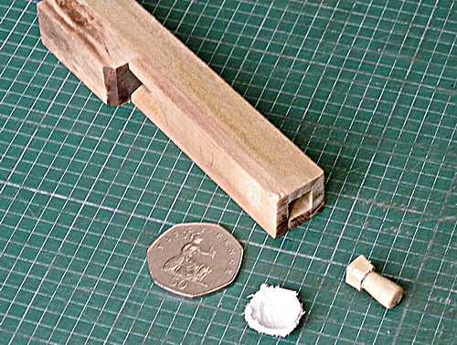
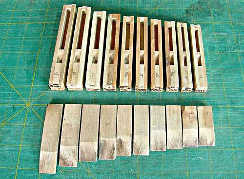
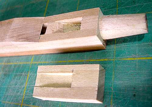
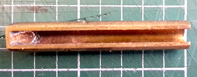
 All the 69 pipes
in this organ were made by myself. Shown here is the smallest of
the main melody bourdon pipes - top "C" (transposed up
3 notes = D# - MIDI 75). A 50-pence coin is shown for size
comparison (approx. 27mm across). The pipe body is 109mm long and
the cross-section is approx. 17mm square. Its internal
cross-section (the important bit) is a mere 8mm square. The
stopper is shown before fitting. Allowance had been made for its
leather plug, shown by the coin. At the other end of the pipe
(out of view) is the foot, made as a separate piece on an
engineer's lathe - a wood-turning lathe would not be accurate
enough.
All the 69 pipes
in this organ were made by myself. Shown here is the smallest of
the main melody bourdon pipes - top "C" (transposed up
3 notes = D# - MIDI 75). A 50-pence coin is shown for size
comparison (approx. 27mm across). The pipe body is 109mm long and
the cross-section is approx. 17mm square. Its internal
cross-section (the important bit) is a mere 8mm square. The
stopper is shown before fitting. Allowance had been made for its
leather plug, shown by the coin. At the other end of the pipe
(out of view) is the foot, made as a separate piece on an
engineer's lathe - a wood-turning lathe would not be accurate
enough.Pipe scaling was accomplished using my scale chart on an Excel spreadsheet. I programmed the original many years ago on a Casio pocket computer, now donated to the National Computer Museum in Bletchley. The scale progression from the largest to the smallest pipe is approximately half-size every 16 notes for the width and half-size every 12 notes for length. Every pipe has unique dimensions (paired for the two ranks of bourdons).
  |
  |
  |
  |
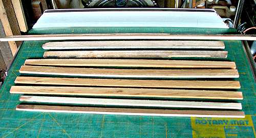
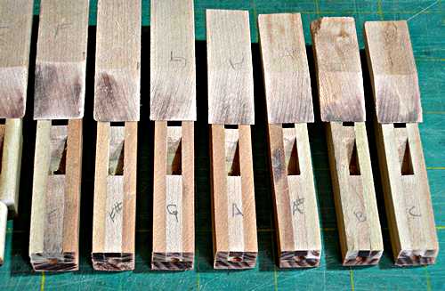
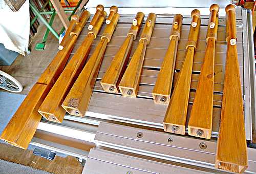
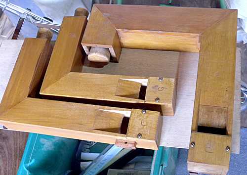 The bass pipes,
shown here, were mitred to fit under the organ's floor. They
are always best in that position so the case plays its part
in enhancing their resonance. These are the largest pipes in the
organ, the longest being 23 inches (583mm), there was not room
enough for them to be left straight, but in any case, their wind
supply coming through a vertical transfer board running across
the front of the case dictated where the pipes' mouths needed
to be.
The bass pipes,
shown here, were mitred to fit under the organ's floor. They
are always best in that position so the case plays its part
in enhancing their resonance. These are the largest pipes in the
organ, the longest being 23 inches (583mm), there was not room
enough for them to be left straight, but in any case, their wind
supply coming through a vertical transfer board running across
the front of the case dictated where the pipes' mouths needed
to be.
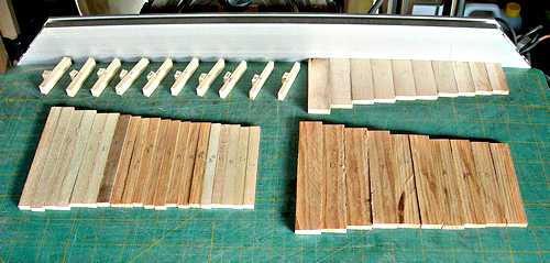
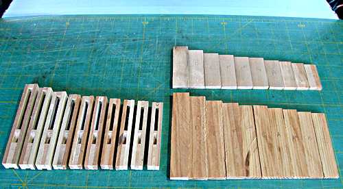
The mitring process, done after voicing, is simple using a mitre saw fitted with a thin blade, so not much length is lost. The only tricky part is where a mitre could interfere with the stopper; the "C" pipe was close!
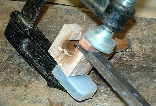
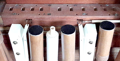
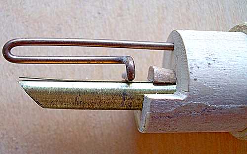 The
"business" end of a reed pipe. Fitted into the block
with a semi-circuler wedge is the shallot - a brass tube open for
its length about one-fifth of its circumference, and fitted with
an angled tip. Shallot-making is a skilled job, and I leave it to
the firm of W P Williams & Co, who
have made all my shallots (to my own specification) over the
years. Across the gap is fitted a brass tongue which is very
slightly curved at the open end. The curve is hand-formed, itself
an extremely skilled job, especially considering all the pipes in
a rank must have the same tone quality and power. The slightest
mis-curve or kink would completely spoil the result. I have
always produced my own tongues, for mechanical and church
organs.
The
"business" end of a reed pipe. Fitted into the block
with a semi-circuler wedge is the shallot - a brass tube open for
its length about one-fifth of its circumference, and fitted with
an angled tip. Shallot-making is a skilled job, and I leave it to
the firm of W P Williams & Co, who
have made all my shallots (to my own specification) over the
years. Across the gap is fitted a brass tongue which is very
slightly curved at the open end. The curve is hand-formed, itself
an extremely skilled job, especially considering all the pipes in
a rank must have the same tone quality and power. The slightest
mis-curve or kink would completely spoil the result. I have
always produced my own tongues, for mechanical and church
organs.
A bronze spring is pressed against the tongue limiting its free length. When wind is applied to the space around this assembly (encased by a "boot") the tongue vibrates in sympathy with its free length and the air column contained inside the resonator (not shown). Tuning is achieved by moving the spring to shorten or lengthen the tongue's vibrating length.
  |
In the summer of 2018, after spending much time arranging music for this organ, I realised that an improvement could be made if the trumpet ran from "C" to "C" instead of "C" to "B". I figured that an additional pipe could be accommodated on the existing music scale by running it into the melody section, with the extra "C" playing with the lowest melody note. The pipe could be winded from the forte pipe block, so it would only operate when the register is "on". A "helper" wouldn't be needed as the melody "C" would be playing with it.
I made some measurements and worked out that if two of the existing reeds were moved out of the way, the extra pipe would fit snugly. So, work began. Making another pipe would not be a problem, but the original shallots had been made by a specialist company, and an order of only one would be prohibitively expensive. So I made made it myself. I had plenty of brass sheet, and found some 16swg (1.5mm), and cut two pieces - one for the tube and one for the tip. With a suitable dowel I hammered the tube into shape, with an approximate opening down the length. Then, after grinding one end to a 45 degree angle, I silver-soldered the tip into position. After cleaning up the shallot and grinding the flat so the opening was the right size it was ready, see the picture.
  |
Making the other pieces presented no problems, and so the pipe was made, and voiced to match the others. I then took out the forte pipes and their mounting block from the organ, together with two of the existing trumpets and the two register pneumatic motors. Measuring the space and doing a spot of carving I was almost ready to fit everything back in, see the picture which shows the pipe in position before the boot was covered to match the others.
| Next | Pages: 1 | 2 | 3 | 4 | 5 | 6 | 7 | 8 | 9 |
© 2018, John Page