
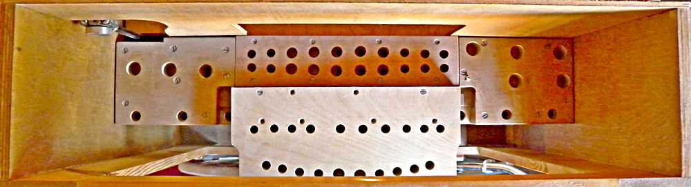
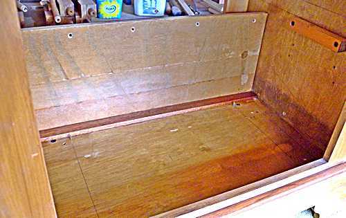
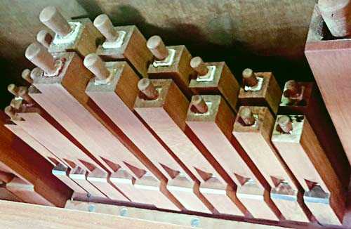
The view above shows my basic pipe layout, which was the starting point in determining the size of case required. Then everything else was designed to fit into it. The reservoir needed to occupy as much space as possible.
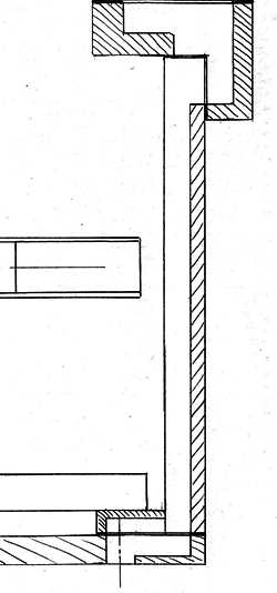
The trumpets would be placed inverted, with their sound projecting out from the space at the bottom of the façade. Behind them would be the vertical transfer board taking wind down to the trumpet helpers and basses below the reservoir. The drawing shows the vertical transfer board (channels to be covered with paper), fitted below the distribution board, with the floor at the bottom. The outlines between show the position of the feeder.NOTE: The photos in this section on assembly may show items not yet described as being fitted, as some were taken during trial assembly tests.
  |
  |
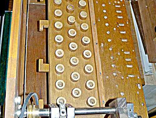
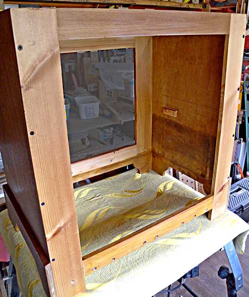
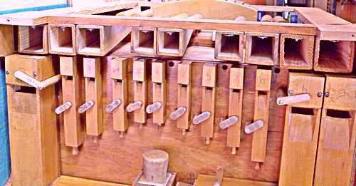
Once the reservoir was installed and the feeders connected to the crank the next job was to install the distribution board and connect the wind trunking between the two. The lower part of the integral relay is shown on the left of this picture, and the wind holes for the pipes are on the right.
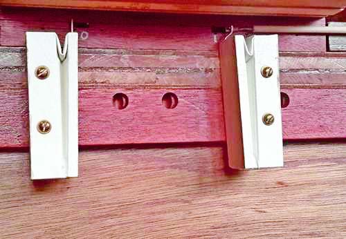
I wanted the back of the relay to be a window, showing just what is inside. The window would be in the form of a sheet of polycarbonate, which would be fitted by quarter-turn latches. The fixed part of the five latches can be seen on the left of the picture.
  |
  |
  |
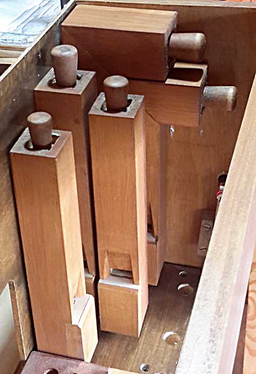
None of these pipes are stayed in any way, their feet having tapers which fitted into tapered holes. The taper of the feet is very slightly different from the holes, so with a light tap or a twist the pipes are secured. They can be easily removed whenever maintenance is necessary.
 Before
the pipes were finally fitted, the action needed to be in place
so the individual pipe holes could be blown through to expel any
dust, and to test the pipes' speech and adjust tuning. A
voicing machine is great for getting the various ranks speaking
with uniformity, but the wind channelling in the organ can easily
upset speech through turbulence and/or pressure loss.
Before
the pipes were finally fitted, the action needed to be in place
so the individual pipe holes could be blown through to expel any
dust, and to test the pipes' speech and adjust tuning. A
voicing machine is great for getting the various ranks speaking
with uniformity, but the wind channelling in the organ can easily
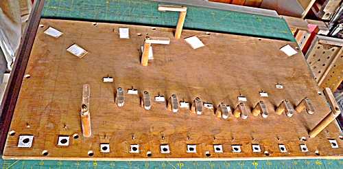
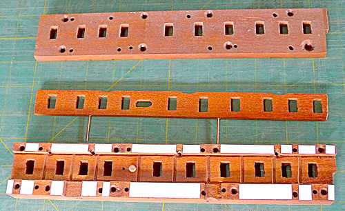
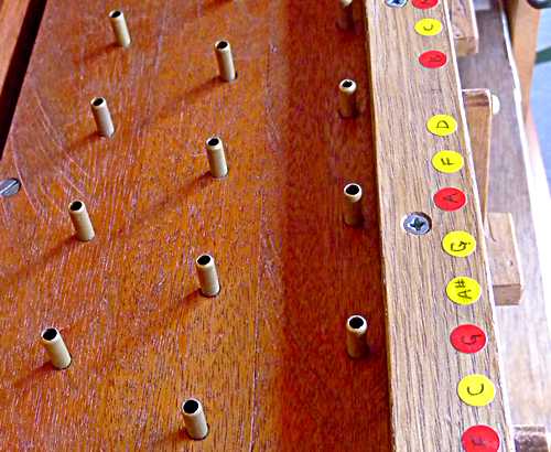
upset speech through turbulence and/or pressure loss.This picture shows the top part of the relay in position. It has short brass tubes fitted ready for the keyframe tubing, and a rail holding the moving part of the window latches. The colour-coded labels indicate the positions of the various notes, to make action adjustments just that bit less tedious.
 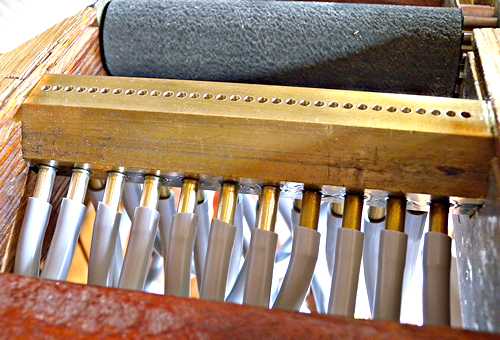 |
Above right: The keyframe end of the tubes fitted to the tracker-bar of the keyframe, in three rows.
 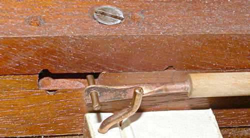 |
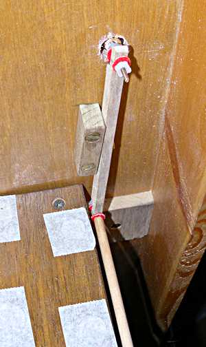
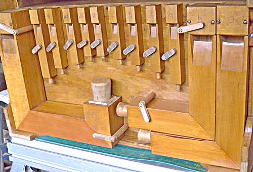
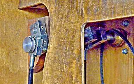
Left: the register action is reversed through the vertical lever (backfall) allowing the knob to be pulled out to bring the forte pipework into play, and pushed in to silence it. The knob will be automatically moved whenever the register is changed through the music itself. The elements of this action are connected by small bronze rods (produced on my thread-rolling machine), and fitted with standard classical organ tracker buttons and washers.
Also showing in this picture are small patches of masking tape covering pipe holes whose pipes are not yet fitted - to keep out dust.
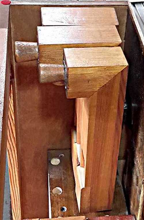
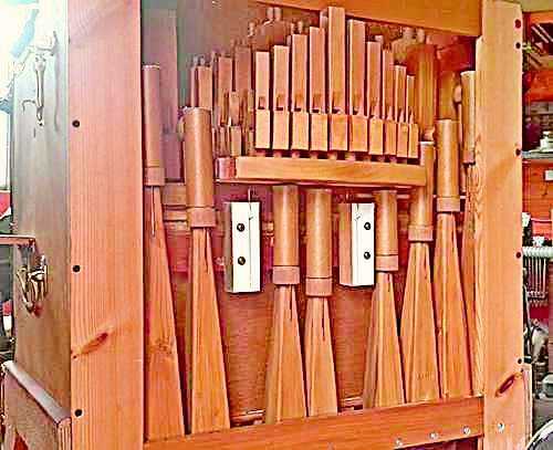
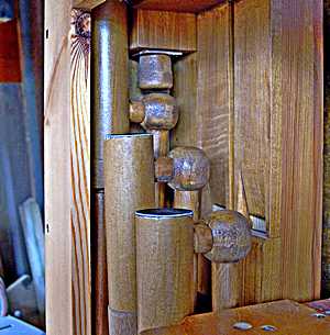
Pneumatic register motors are mounted on the front of the distribution board. They were strategically placed to fit between the trumpets. The manual register control can be seen at top right of the picture.
The large holes are for the three smallest trumpets, feeding directly into their boots from the back.
  |
Regulating these reeds was somewhat tricky, especially the longest ones mounted in the corners. As they speak into the space below the organ's floor, the surrounding timber shields them, simulating longer resonators. To reduce the excess "length" I needed to shave away a considerable amount while leaving the front slat at its original length so the bolt mounting could still be used. I had to do that by small amounts at first, replacing the pipes into position with the others around them, trying them on the wind each time, until I got it right. Only then did I finally secure the pipes and their wind supply tubes with a thin smear of Evo-stik, which is easily pulled away whenever the pipes need to be removed. The rubbery glue would still serve to seal the joins when the pipes are re-fitted.
As this organ has an enlarged musical scale based on the popular English 20 note organs, it is unique to this organ, no commercial arranger will accept a job unless there will be at least 5 organs he could sell it to, so I am forced to do it myself.
This is an organ built on traditional lines, and as such is a demonstration of how it used to be done. That's why I decided to not have anything electrical on the organ, so MIDI is out. I specifically wanted to be able to play tunes at random, and not in any specific order, so paper-rolls were also out, leaving cardboard the only option. As this organ was designed on the German style, with a separate trumpet section and a forte register, I went for keyless operation as opposed to the French/Dutch keyed. A keyless keyframe is far simpler in design and construction, which was another good reason for using the keyless system.
I and the famiy have produced a short video showing how the music is arranged and cut: on Youtube. Please feel free to leave comments.
| Next | Pages: 1 | 2 | 3 | 4 | 5 | 6 | 7 | 8 | 9 |
© 2020, John Page